Assembly
I’ve ordered (and received) a quantity of the circuit boards for this project; they’re available for $5.00 each, shipped. Parts placement is indicated on the board; the parts are also designated in the schematic (see the Hardware page for a link to the schematic).
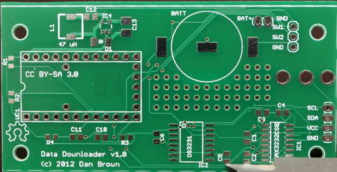
Note that R3, R4, C10, and C11 are not used at this point. They’re intended for future expansion, to allow reading from two pushbutton switches (which would be connected to the SW1 and SW2 pins in the upper right). The area of vias below the battery is also not used at this point. It is designed to allow space to add components to the board for additional expansion.
The power supply circuit is in the upper left corner of the board, consisting of IC4, D1, L1, C12, and C13. D1 and C13 are polarity-sensitive--the polarity for D1 is marked on the board, but C13 is not. C13 should be installed with the polarity marking facing toward the bottom edge of the board. The remaining capacitors, and both resistors, are non-polarized, and can be installed in any orientation.
Further information and photos will be added as time permits.